Tyre Pressure Gauges
Tyre pressure gauges come in various forms. The most common were the 'pencil' gauges - which indicate pressure on a telescopic barrel - when the gauge is applied either to a pressure test valve on the pump, or direct to the tyre valve. The other common type is the circular dial gauge - where a pointer indicates pressure on a circular scale. These can be an integral part of the pump, or separate - to be applied as the pencil gauge.
Pencil Gauges
Some examples from various makers are shown below.
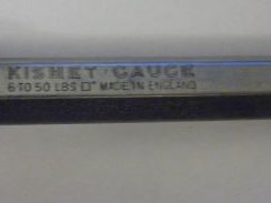
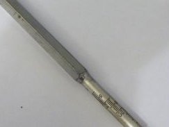
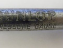
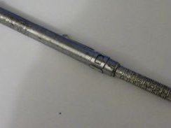
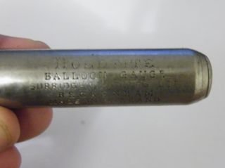
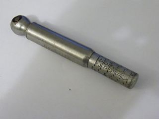
The head of the gauge is applied to the valve on the tyre and the inner barrel is forced out to a point which indicated the pressure – via a graded scale on the inner barrel. This scale is often spiral in nature so accurate readings are indicated. Gauges of this type are almost maintenance free – but I sometimes undo the central screw in the gauge head – take out and oil ( or replace) the little leather seal washer and squirt some WD40 in whilst I’m at it! As to accuracy – I’ve found that after doing this they always read accurately when calibrated against a more modern (e.g. digital) gauge. If you don’t have one of these – compare the readings from two or three old gauges and check consistency. If they read consistently – its usually right! If one is different – set it aside for more oiling/calibration! If desparate – go to a garage air line and check readings there! The main trick with these old pencil gauges is to get a square, solid connection when offering them up against the tyre valve – so there is no air loss and a true reading is obtained.
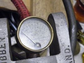
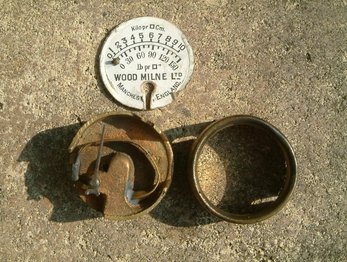
Circular Dial Gauges
Some example dial gauges are shown below. The first picture shows a gauge on a British Goodrich pump, the second shows a dismantled one from a Wood Milne (very similar to the British Goodrich) and the third shows a Sutty
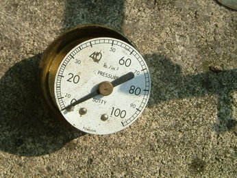
All these gauges work on the same principle - that of the Bourdon tube. Eugene Bourdon, a French engineer, patented his gauge design in 1849, and it was widely adopted. Edward Ashcroft purchased Bourdon's American patent rights in 1852 and became a major manufacturer of gauges. The system became widely used in pneumatic engineering applications, including car foot pumps.
The schematic principle of the gauge is shown below
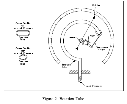
The C-shaped Bourdon tube has a hollow,elliptical cross section. It is closed at one end and is connected to the air pressure at the other end.When pressure is applied, its cross section becomes more circular, causing the tube to straighten out somewhat, like a garden hose when the water is first turned on. It continues to straighten until the force of the air pressure is balanced by the elastic resistance of the tube material. Since the open end of the tube is anchored in a fixed position, changes in pressure move the closed end through a shallow arc - which is virtually a straight line. Since the tube material remains elastic - the movement of the tube end along the straight line is proportional to the pressure applied i.e. there is a linear relationship between tube end movement and pressure. A pointer is attached to the end of the tube through a ‘slider crank’ linkage arm – consisting of two links - and (sometimes) a gear and pinion assembly. This arrangement is intended to convert the linear motion of the closed end of the tube to a linear rotation of the pointer around a graduated scale i.e. the rotation of the pointer (in degrees)should be proportional to the applied pressureThe gear ratio of the gear and pinion assembly has the function of magnifying the rotation of the pointer.
Accuracy
The scale on the pressure indicator card behind the pointer, the initial pointer shaft position, the linkage lengths and initial positions all provide means to calibrate the pointer to give a linear pressure/rotation relationship and therefore indicate pressure as accurately as possible at all points. However, the precision of measurement is usually not high on small bourdon gauges because the linkage lengths are not always precisely designed or adjusted to accurately convert the linear pressure/displacement relation of the end of the tube to a linear pressure/rotation relation of the pointer. In fact, it can be shown theoretically that a two link ‘slider crank’ mechanism can only be calibrated to show pressure perfectly accurately at two points on the circular pointer scale. I know this, because I studied the problem as part of my final year design project as an undergraduate engineer in 1970!
Nevertheless, despite these issues, the Bourdon Gauge on a vintage pump, if working, generally gives a reasonable indication of the true pressure. It also provides an attractive feature - but is prone to damage. Generally, the user is advised to double check with a pencil or other gauge, initially at least, to make sure the Bourdon Gauge reading is in the right ballpark. Also to use a pencil gauge if accurate pressure measurement is important.
From my experience, I would say that the reading on a small Bourdon pump gauge should be interpreted as having an accuracy at best of +/- 5psi, particularly when the difficulties of reading the small scale gradations are taken into account.
Bourdon tube gauges, their linkages and the circular pressure scale can all be refurbished and restored if not too badly damaged. Get in touch if you need me to look at one and I'll advise if it can be repaired.